This project page provides a guide to adding both USB and a Web based User Interface (UI) to remote control socket set. In the process we will unlock even more capabilities than are available when you use the socket set as they were originally intended. Part 1 (this post) deals with the hardware, Part 2 deals with programming the chip and Web UI.
It essentially builds upon this blog by [befinitiv]
Radio controlled sockets are a great way to save power in your home. Devices consuming more power on standby than the sockets do can easily be switched off with a remote. For example my desk lamp from a swedish furniture store consumes 10x more power (in the off state) than a radio controlled socket.
Even if the sockets consume more power in standby than the attached electronic device, they offer the luxury of turning stuff off and on without even moving. In short: They are really handy.
However, if you’ve installed the sockets, one sentence will often reoccur: Where the f*** is my remote?
The goal of this post is to show you a way of adding USB support to remote controlled sockets. This opens up a whole new world to remote controlled sockets. Plug this kind of remote into a computer and you can do amazing things.
This gives a pretty good justification for doing this, plus I wanted a worthwhile project to learn a little about programming standalone AT Megas (most of my experience has been with Arduino and PicAxe to date). The main difference here is that I thought I could improve on the system by adding a Web UI to the mix (now I can control it from any device that has a web browser) and that I use a slightly different model of remote.
The main components are:
- Energy Efficient Remote Control Mains Socket Set
- AT Mega 8
- Nokia CA-42 Data Cable (cheap ones here)
- Arduino (or other AVR-MK2 programmer)
- Web-server (I used a Raspberry pi, but any computer will work if it’s running Apache and PHP)
- Lego (if you want to make a Raspberry pi case)
So you may (or not) have noticed that I have ordered different sockets to those used by [befinitiv] in his guide, the reason for this is that I live in Ireland and the sockets he was using have a European connection. When I opened the remote I noticed that the encoder used was different to the one in [befinitiv]’s guide (SC5262 chip datasheet), my heart sank a little. Thankfully I found the datasheet for the HX2262 (datasheet) and it turns out to be identical, so crisis averted!
As [befinitiv] mentions the CA-42 Cable is used because it contains a serial to USB chip. I was happy to pick a few of these cables cheap from Meritline, but after opening them up I found that they were missing the power line (3 core rather than 4), so I swapped out that cable for a 4 core cable, I then found that the voltage on the on the other end was not as high as would be expected (about 3.2v rather than closer to 5v), this low voltage wouldn’t keep the atmega8 powered. I figured it might be the traces on the PCB were so small they were creating extra resistance. Once I bypassed the PCB traces and went directly from the cable to the USB plug all was fine (see below). You can also see that the TX is hooked up to the green cable and the RX (not really used in this guide) is hooked up to the white cable.
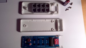
Once that’s sorted it’s time to start wiring things up. There are differences in which pins are used on[befinitiv]’s remote and the ones that I acquired , but after some testing, the relevant pins were identified. It’s handy to have the ATMEGA8 datasheet. So starting with the ATMEGA8 start wiring it up as you see below (I decided to go with some vero board rather than ‘dead bug’ it like [befinitiv]). Don’t solder the USB up just yet, we will wait until last as you will want to feed the cable through a whole in the casing before you solder it to the chip. Note the purple, grey, white and black cable coming from the bottom, this is the cable we will use to program the chip.
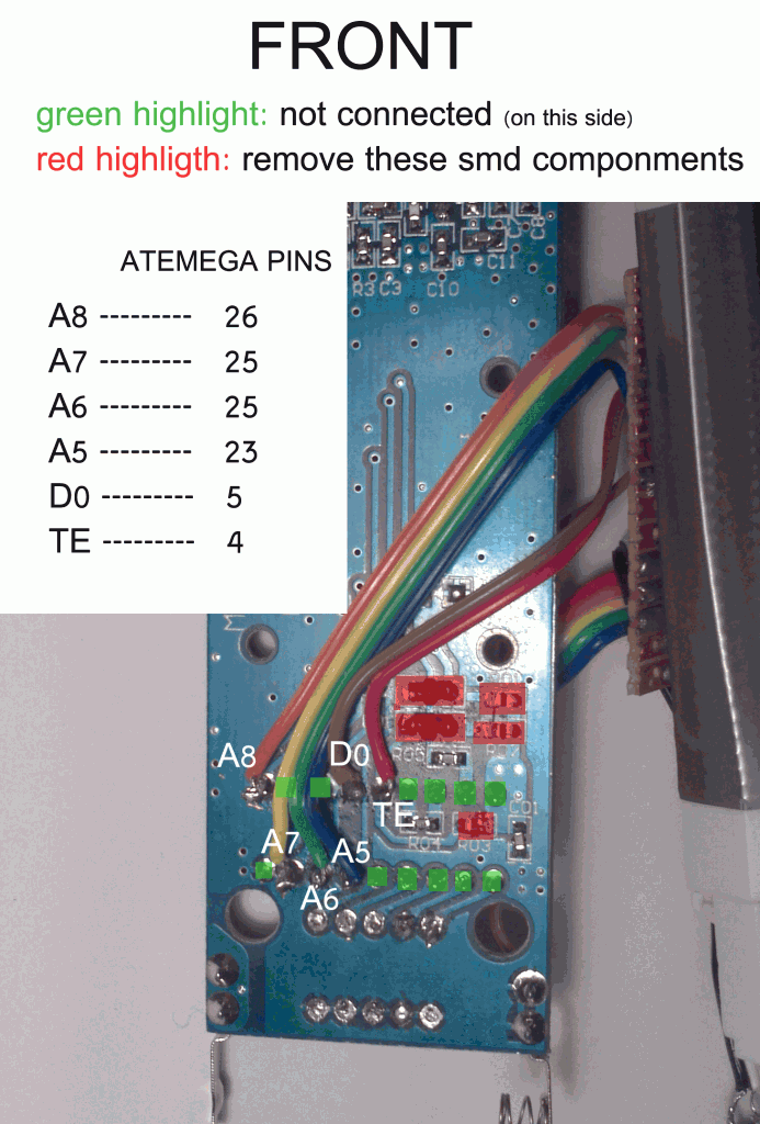
Then on the front of the remote board (see below) remove the 5 SMD (surface mount device) components highlighted red and connect up teh wires as shown (the green highlights show no connection on this side).
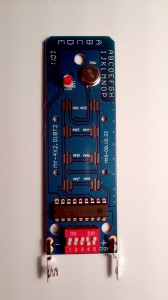
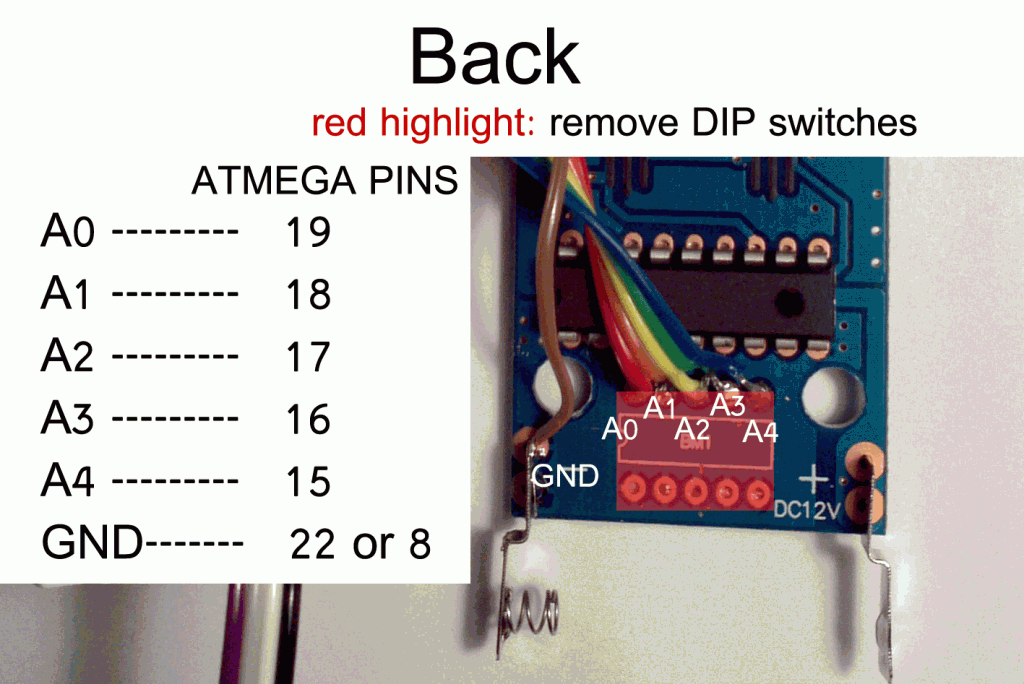
Similarly on the back of the remote board remove the DIP switch (the big red block in the first images) and wire it up as shown.
Now to fit it all back into the case. Using a pliers snap away the casing that surrounds the buttons (see below). It seemed to come off rather cleanly for me.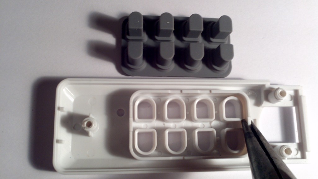
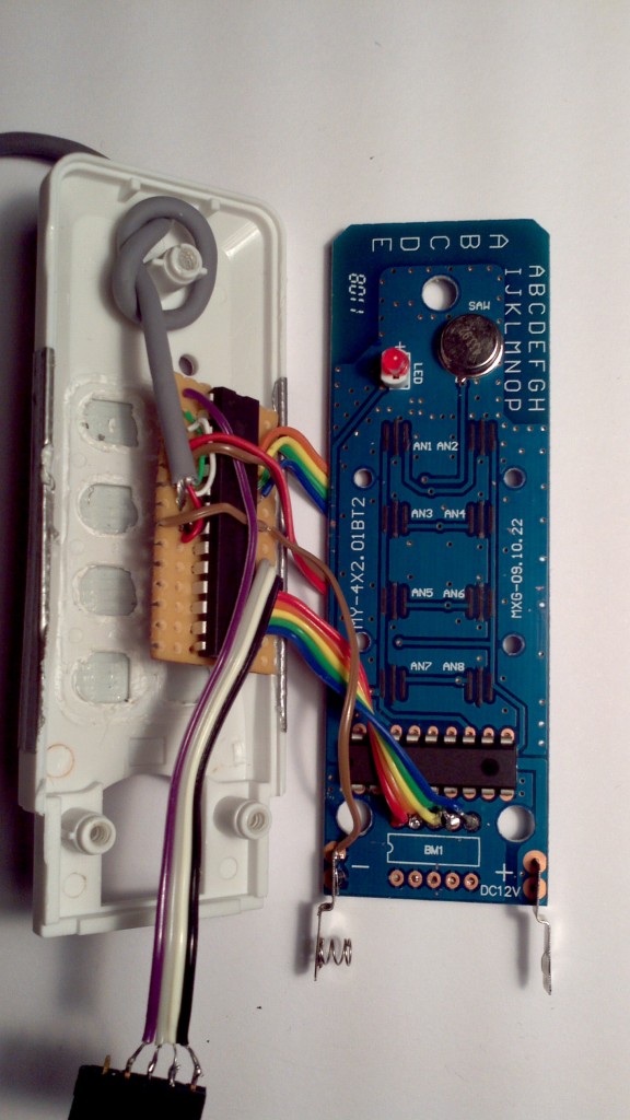
Then make a hole (drill or melt) in the casing to pass the USB cable through, make a small knot in the USB cable to put around the small post in the casing (see below) in order to stop any tension on the cable damaging any of your connection, then solder up the USB connection to the ATMEGA8. You can see here the complete assembly before we put it back in the casing (again note the programming cable at the bottom).
So now close it up and it should look something like this…
Now we are ready to start programming… See Part 2
Bonus picture, in case you thought it was a tidy process all the way through 😛



Hi there!
I enjoy seeing you are continuing my work. Your documentation seems to be very detailed, nice!
In fact, web control was the first thing I used my remote control for. And I still do. To use your mobile phone as a remote is nice because I always have it in my pocket.
Some other use cases I have for the remote:
– Using cron to switch on devices on a specific time. I used this as a alarm in the morning. First the not-so-bright desk lamp switched on and five minutes later the really bright desk lamp switched on. For me it’s nicer to wake up by light than by sound.
– I use my dockstar also for playing music via MPD. A HiFi amp is plugged into the USB soundcard. Whenever MPD starts playing music, I turn on the amplifier. If after some time not music has been played, the amplifier is turned off automatically. This is also very convenient.
I’ll stay tuned for your next post!
Best regards,
befinitiv.
Hi, well thank you for getting me started!
Some good ideas you have there, I had thought about the cron jobs for alarms and security (if the house was left unattended).
I also took the circuit out of one of the sockets and installed it inside the main light switch for my bedroom, meaning I have control over the lamps, screens, amps and main lights of my room now.
I think one of the really interesting things about this hack is the extra functionality you can unlock. Technically there are 2^4 (16) devices that can be controlled on each channel and after some testing it seems I can potential unlock 2^5 (32) channels. Meaning that ultimately we could control 512 different devices easily via software (not that I could afford to buy that many sockets right now). This is compared to the 4 devices you get with the remote as you buy it (although technically you can use button combinations). But I’ll go into more detail about that in my next post (should get around to finishing it in the next week)
Thanks for taking the time to comment 🙂
Hi
My devices have some sort of channel selector. This isn’t a real frequency channel but just 4 more bits of the address word. Every socket has a channel selector and a device selector (each having 4 positions) at the back. So I could use up to 16 sockets without any changes made to them. But currently I’m using only three because of the standby current they consume.
Best regards,
befinitiv.
How much is the standby current? is it big?
I’m oscillating between doing this and something similar with Zigbee+relay modules…
BR
Hi Adrian,
Thanks for the interest. I did a little testing of the units I’m using.
They use 23mA in standby. I also checked how much power they consume and a plug-in energy monitor I have gives the standby power as 1.9 Watts and an in use (but without an appliance) power supply of 1 Watt (same current).
So they seem to use less current than Xbees but must be at a higher voltage, hence the surprising large power consumption. Obviously sleep and standby modes would be lower.
That said, if you are going to use Xbees you will need to power them from the mains at much a lower rectified voltage and that conversion process will probably cost you (powerwise, depending on how you go about it). So you’d have to take that into account.
Also you would have to manufacture each socket with the Xbees approach, which is both tedious and somewhat dangerous as you’re dealing with mains voltage. The approach I’ve taken here means you only have to tinker with the remote control (no high voltages and only on device, also you have consumer grade housings for your socket hardware).
As for hardware cost, all the hardware (3 remote sockets, a remote control, an Atmega8 and a CA-42 cable) in my approach costs almost the same as a single Xbee module (give our take a few euro/dollars).
If the issue is power costs, maybe if you do a really good job with the Xbees you might reduce the power consumption significantly. But the cost of hardware would take years to make them worthwhile (as compared to this approach). Also if you are concerned about multiple sockets draining power continuously you could consider a system where you use one socket in series with the others, so disabling the first in the series turns off the power to all the others, leaving only one on (although you have to watch the current draw here as the sockets I have can only draw a max of 10A).
That’s my comments on you’re options, I’m open to issues I may have over looked or glaring assumptions I’ve made.
Best of luck regardless,
Jake
[…] more capabilities than are available when you use the socket set as they were originally intended. Part 1 deals with the hardware, Part 2 (this post) deals with programming the chip and Web […]
[…] controlled power outlets to his network. He wrote about his project in two parts, the first is hacking the RC outlet controller and the second is using the Raspberry Pi to manipulate […]
[…] controlled power outlets to his network. He wrote about his project in two parts, the first is hacking the RC outlet controller and the second is using the Raspberry Pi to manipulate […]
[…] controlled power outlets to his network. He wrote about his project in two parts, the first is hacking the RC outlet controller and the second is using the Raspberry Pi to manipulate […]
[…] controlled power outlets to his network. He wrote about his project in two parts, the first is hacking the RC outlet controller and the second is using the Raspberry Pi to manipulate […]
[…] controlled power outlets to his network. He wrote about his project in two parts, the first is hacking the RC outlet controller and the second is using the Raspberry Pi to manipulate […]
[…] » Adding web connectivity (via USB) to remote controlled sockets – Part 1 (hardware) Jake Rowan B… This project page provides a guide to adding both USB and a Web based User Interface (UI) to remote control socket set. Through the process we will unlock even more capabilities than are available when you use the socket set as they were originally intended. Part 1 deals with the hardware , Part 2 (this post) deals with programming the chip and Web UI. I don’t have a AVR-MK2 programmer like [befinitiv] , but I do have a number of Arduino boards. There are a number of ways to program an AT Mega 8 with an Arduino, but the most successful method I have found is to use mega-isp code for Arduino. […]
[…] » Adding web connectivity (via USB) to remote controlled sockets – Part 1 (hardware) Jake Rowan B… Kit Review – akafugu TWILCD Display Controller Backpacks Introduction Working with LCD displays is always useful, for debugging hardware by showing various data or part of a final design. Furthermore, using them can be rather wasteful of I/O pins, especially when trying to squeeze in other functionality. Plus there’s the external contrast adjustment, general wiring and the time taken to get it working. (Don’t believe me? Blog » Blog Archive » Finger print sensor with Arduino A lot of times I have people asking me about interfacing a fingerprint sensor to an arduino for their school projects. Thanks to Adafruit that its now just a connection + an arduino away. The beautifully done libraries can be found here . […]
Hi Jake, I have been following your post. I am using the Efergy Remote control Sockets. It uses a different Chip from the one you have use. It uses HT48R01T3
Because of the difference in the chip, I am no sure which SMD to remove.
Hi Kelvin,
without seeing the board itself it’s hard for me to say. The main thing is to not alter anything that connects with the RF circuit. It’s been a while since I’ve looked at the circuits so I’m a little rusty, but essentially it should be the components that link up with the button pins you are intercepting. If you can remove them in a way that they may be reconnected (release on side) it might help you experiment a little. I hope that helps somewhat.